The aerospace sector imposes some of the most stringent requirements on materials, dimensional accuracy, and process documentation. Flight-critical components undergo multi-stage certification, and polymer-based 3D printing does not replace that process. However, beyond flight hardware there is a broad domain of tasks where industrial FFF printing with high-temperature polymers can deliver practical value: prototyping, ground support equipment, tooling, assembly fixtures, and R&D.
Developing a new aerospace product typically involves years of design work with dozens of geometry iterations. Every fit-check, every layout verification demands a physical part. The conventional route — ordering CNC machining or casting — takes weeks, and the per-unit cost for one-off parts remains high. Industrial 3D printing with PEEK, ULTEM, and PA-CF enables a different workflow: a CAD model goes directly to the printer, and a physical part can be ready within hours.
For aerospace manufacturers operating in global supply chains, this capability can be especially relevant when imported components and custom tooling face extended lead times, and R&D timelines demand rapid iteration.
Typical Applications for 3D Printing
Component prototypes for testing. Full-scale models for verifying geometry, layout, fit, and fastener accessibility before committing to metal. Multiple iterations in days rather than months.
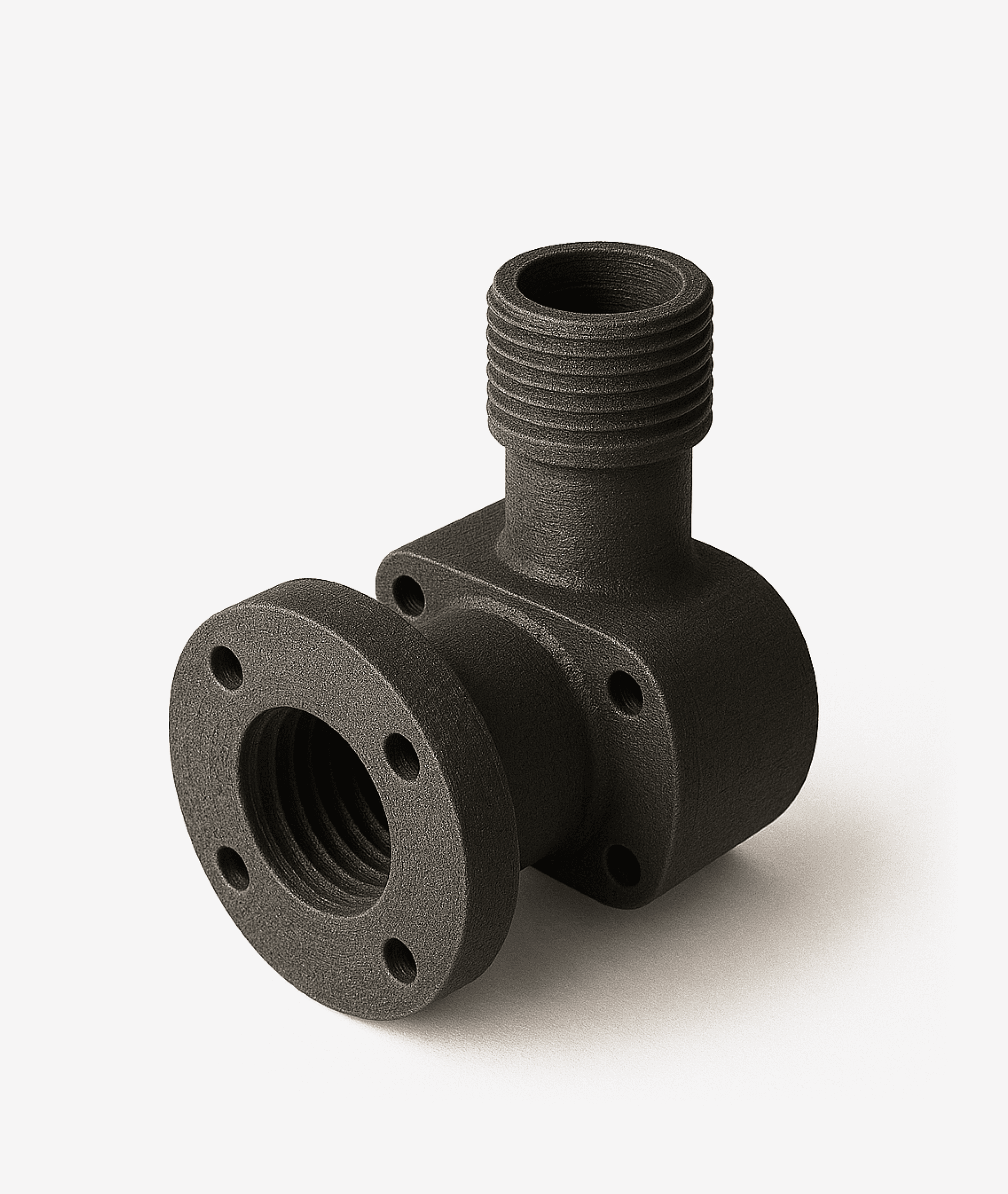
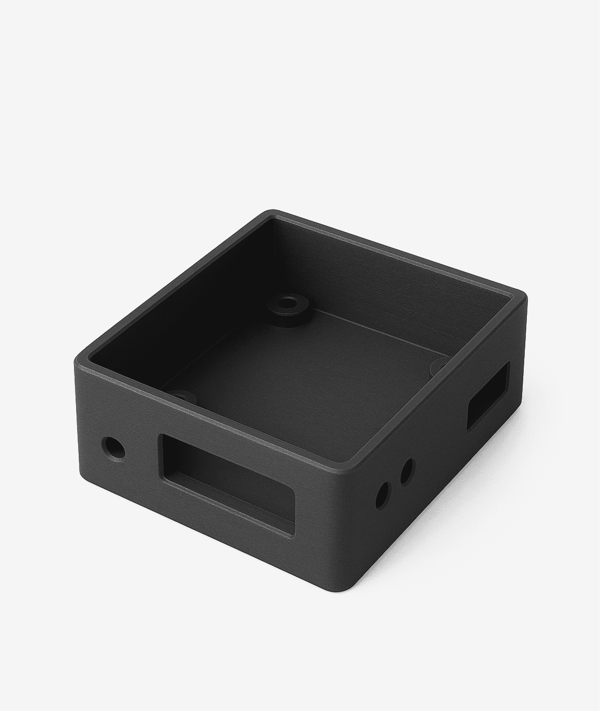
Ground support equipment (GSE). Brackets, fixtures, and mounting elements for ground servicing — applications that typically do not require flight certification but demand accuracy and resistance to the operating environment.
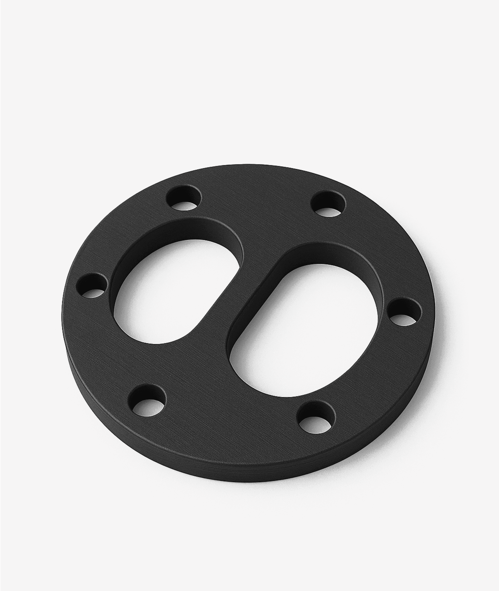
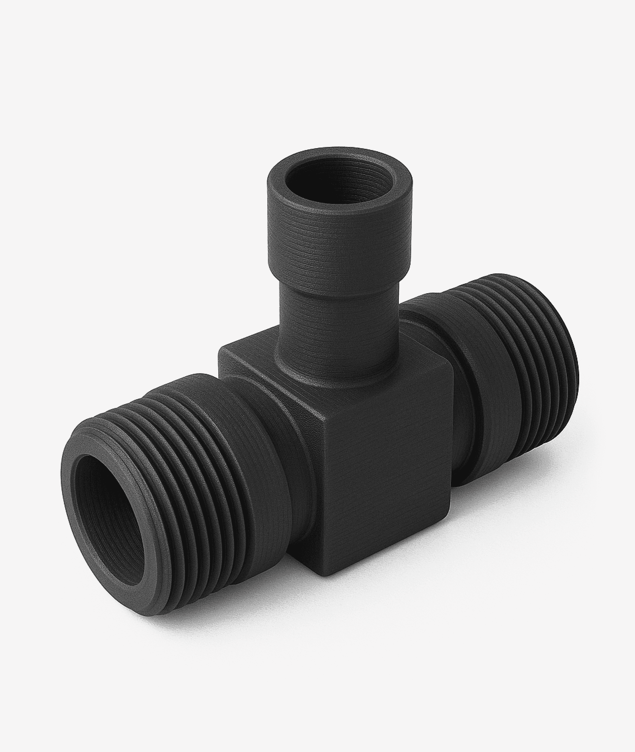
Tooling and assembly fixtures. Drill jigs, bonding fixtures, positioning jigs for the assembly line. Printing from PA-CF or PC-ABS instead of ordering CNC machined parts.
Duct prototypes. Verifying the geometry of ventilation channels and air ducts before fabrication from production materials. ULTEM 9085 can be considered for prototypes where flame retardancy is relevant.
Cable routing fixtures and layup templates. Wiring harness routing is labor-intensive. 3D-printed fixtures and templates can help accelerate cable layup and route verification during early design stages.
Interior element prototypes. Non-flight mockups of panels, trim pieces, and cabin components for ergonomic and design evaluation.
R&D and materials testing specimens. Standardized coupons from PEEK, ULTEM, and PA-CF for mechanical, thermal, and chemical testing programs.
Important: Scope of Application
3D-printed parts in the aerospace context are intended primarily for non-flight tasks: prototyping, tooling, ground support equipment, R&D
Protype does not claim aerospace certification (AS9100, etc.) for its printers
The suitability of printed parts for any specific application is determined by the customer's engineering assessment
Production Application Scenarios
01
Tooling for ground servicing operations
A specialized fixture is needed for servicing an engine assembly. The conventional path: design, order aluminum CNC machining, wait 3-6 weeks. With a 3D printer: the CAD model of the fixture is printed from PA-CF in 8-14 hours. The part is verified on-site; if geometry adjustments are needed, a revised version can be reprinted the next day. For conditions requiring elevated thermal resistance, PEEK on the CD400HT can be considered.
02
Air duct prototype in ULTEM
The engineering department is developing a new ventilation system configuration. Before fabricating the production duct from metal, the routing path, compatibility with surrounding structures, and cross-sectional clearances need verification. A full-scale prototype is printed from ULTEM 9085 on the CD400HT. The actively heated chamber at up to 150 deg C with uniformity of Delta-T less than 1 deg C provides stable conditions for printing this high-temperature material. The result: physical layout verification in 1-2 days instead of weeks.
03
Assembly jigs for the production line
A fuselage panel assembly line uses dozens of positioning fixtures. Every panel design change requires new jigs. Printing from PC-ABS on the CD400 enables same-shift jig fabrication. IDEX Copy mode doubles throughput: two identical jigs printed simultaneously. XY positioning accuracy of 5 microns helps ensure correct fixture fit.
04
Specimens for materials characterization
An R&D laboratory is running a test campaign to determine the mechanical properties of polymer materials under various conditions. Dozens of standardized specimens from PEEK are needed with controlled print parameters: layer orientation, infill density, temperature profile. The CD400HT with its chamber up to 150 deg C, build plate up to 250 deg C, and layer thickness range of 0.05-0.75 mm allows parameter variation for each batch while maintaining process reproducibility.
Want to evaluate what 3D printing can do for your aerospace applications?
Accelerated prototyping cycles. In aerospace development, the number of design iterations directly affects the quality of the final product. When each iteration takes hours instead of weeks, engineers can evaluate more design variants and identify issues at earlier stages — when corrections are orders of magnitude less expensive.
Reduced dependence on external suppliers. Tooling, jigs, and prototypes are produced on-site. This can help shorten lead times, especially in situations where subcontractors are at capacity or original suppliers have extended delivery schedules.
High-temperature polymers for demanding applications. PEEK withstands continuous service temperatures above 250 deg C, resists most aggressive chemical environments, and offers a high strength-to-weight ratio. ULTEM 9085 meets FAR 25.853 flammability requirements (material manufacturer data). These properties can make printed parts suitable for a range of applications where standard engineering plastics are not viable.
Controlled print environment. The CD400HT chamber with temperature uniformity of Delta-T less than 1 deg C is a critical parameter when printing PEEK and ULTEM. Uneven heating leads to warping, delamination, and internal stresses. The actively controlled thermal environment enables consideration of printing larger parts with predictable geometry.
3D Printing and Artificial Intelligence: Aerospace Applications
The aerospace sector is among the most demanding when it comes to optimizing weight, strength, and reliability. AI tools combined with additive technologies can help address a number of these challenges more effectively.
Topology optimization for weight reduction. In aerospace, every gram matters. AI-driven topology optimization algorithms can propose bracket, fixture, or tooling geometries that minimize mass for given load conditions. The resulting organic shapes are typically difficult to CNC machine but well-suited to FFF printing from PA-CF or PEEK.
Generative design for brackets and mounting elements. AI generates multiple design variants based on specified boundary conditions — mounting points, allowable loads, space constraints. The engineer selects the optimal variant, which is then printed for physical validation. Several "generate-print-test" iterations per week instead of one per month.
Automated quality monitoring. Machine vision systems can analyze layers during the print process, detecting delamination, under-extrusion, and deformation. For aerospace tasks where quality requirements are particularly stringent, such monitoring can help increase confidence in printed parts.
Print parameter optimization. High-temperature polymers (PEEK, ULTEM) are sensitive to process parameters. Machine learning algorithms can identify optimal temperature profiles, speeds, and infill strategies, reducing the number of trial prints and consumption of costly material.
Material behavior prediction. Neural network models trained on mechanical test data can help predict the strength characteristics of a printed specimen based on layer orientation, infill percentage, and temperature regime — before the part is actually printed.
Why Protype CD400HT for Aerospace Applications
Full super-polymer capability. Hotend up to 550 deg C, chamber up to 150 deg C with uniformity of Delta-T less than 1 deg C, build plate up to 250 deg C, drying chambers 2x up to 130 deg C. This is the complete thermal stack required for stable printing of PEEK, PEKK, and ULTEM. Many printers claim PEEK compatibility but do not provide uniform chamber heating — the result: delamination and internal stresses. The CD400HT is engineered for these materials.
Accuracy for critical tasks. XY positioning 5 microns, Z positioning 2 microns. Minimum layer thickness 0.05 mm. These parameters provide the geometric precision needed for tooling and assembly fixtures in aerospace production.
Build volume 350x350x400 mm. Sufficient for most component prototypes, air ducts, and ground support equipment elements. Large parts can be printed with 0.8-1.2 mm nozzles to accelerate the process; precision parts with 0.3-0.4 mm nozzles.
IDEX for production tasks. Two independent extruders. Copy mode — two identical parts simultaneously. Mirror mode — mirrored pairs (e.g., left and right brackets). Doubled throughput is valuable when producing tooling in series.
Autonomy and fleet management. Auto-feed filament system 4x3 kg, automatic bed leveling, nozzle cleaning. ProtypeOS + ProtypeHub for multi-printer fleet management. Secure VPN for integration into protected corporate networks — a standard requirement at aerospace facilities.
Open material architecture. No lock-in to a specific filament supplier. The facility selects material from a qualified manufacturer according to its own internal standards.
CD400 vs. CD400HT Comparison
Parameter
CD400
CD400HT
Build volume
400x400x400 mm
350x350x400 mm
Chamber temperature
up to 90 °C
up to 150 °C (ΔT < 1 °C)
Build plate temperature
up to 150 °C
up to 250 °C
Hotend temperature
up to 550 °C
up to 550 °C
Drying chambers
2x up to 80 °C
2x up to 130 °C
Key materials
PA-CF, PC-ABS, ABS, PA6, TPU
PEEK, PEKK, ULTEM + all CD400 materials
Aerospace recommendation
Prototypes, assembly tooling
PEEK/ULTEM parts, high-temperature applications
Warranty
12 months
12 months
Try & Buy: 3-month evaluation program
Protype offers a Try & Buy program: use the printer in your production environment for 3 months, and if you purchase, 100% of the rental cost is credited toward the purchase price. For aerospace organizations, this provides an opportunity to evaluate the technology on real-world applications without upfront capital expenditure.
Frequently Asked Questions
Ready to evaluate 3D printing for your aerospace applications?
Take advantage of the Try & Buy program: 3 months of on-site evaluation with 100% rental credit toward purchase.
We integrate Protype into production cycles across industries—from Education to Aerospace
Where Protype printers work
01
Mechanical engineering
Applications
Jigs, gearboxes, brackets.
Why it's worth it
Tooling in hours, not weeks. Small-batch costs drop 5–10x while accuracy stays the same.
02
Architecture
Applications
Building models, facades, landscapes.
Why it's worth it
Clients see a physical model before ground is broken — approvals happen faster.
03
Railway
Applications
Fasteners, sensor housings, cable channels.
Why it's worth it
The railcar doesn't sit idle while the part ships from a warehouse. Print on-site — minimal downtime.
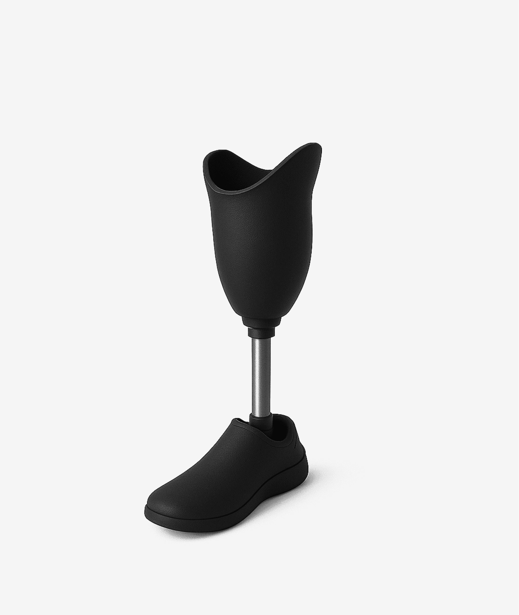
04
Medical
Applications
Orthoses, prosthetics, anatomical models.
Why it's worth it
Every piece fits the patient's anatomy exactly. No molds needed, ready in a day.
05
Education & R&D
Applications
Fixtures, gears, trays.
Why it's worth it
A failed prototype isn't a setback — it's the next iteration. A new one prints in an hour.
06
Petrochemicals
Applications
Mechanisms, housings, training models.
Why it's worth it
Test the material and shape in days rather than waiting months for production tooling.
07
Shipbuilding
Applications
Supports, gaskets, small hardware.
Why it's worth it
The yard doesn't wait on a supplier — parts print right in the dock, repairs stay on schedule.
08
Instrumentation
Applications
Enclosures, covers, PCB holders.
Why it's worth it
Changed the PCB layout? Reprint the enclosure. No retooling, no missed deadlines.
Don't see your industry?
Tell us what your facility produces — we'll find a solution to cut costs and speed up part production
Mechanical engineering
Applications
Jigs, gearboxes, brackets.
We print tooling and structural elements for assembly and repair: positioning jigs, gearbox housings, fixtures. This speeds up new line launches and allows quick reconfiguration of assemblies.
Why it's worth it
Tooling in hours, not weeks. Small-batch costs drop 5–10x while accuracy stays the same.
Don't see your industry?
Tell us what your facility produces — we'll find a solution to cut costs and speed up part production
We'll calculate the savingsfrom 3D printingfor your production
We'll evaluate your parts, compare with your current method, and show where 3D printing is more cost-effective.