Why Mechanical Engineering Is Adopting Additive Manufacturing
Mechanical engineering operations contend with tight deadlines and exacting precision requirements. Whether launching a new product line, upgrading production equipment, or addressing unplanned maintenance, teams frequently face the same bottleneck: waiting for tooling and replacement components.
The conventional path -- ordering injection molds, sourcing CNC machining, qualifying a new supplier -- typically takes weeks or months. For low-volume runs, the per-unit cost can become prohibitively high relative to the part's function.
Industrial 3D printing (FFF/FDM with engineering-grade polymers) enables a different approach. A digital model is sent directly to the printer, bypassing intermediate tooling altogether. This can significantly shorten the path from design to finished part -- particularly where the requirement involves one-off components, prototypes, maintenance spares, or short production runs.
For manufacturing facilities, supply chain responsiveness is an additional consideration. When a critical assembly goes down and the original component is only available with extended lead times, localized 3D printing with engineering plastics can help restore equipment uptime in hours rather than weeks.
Typical Applications Addressed by 3D Printing
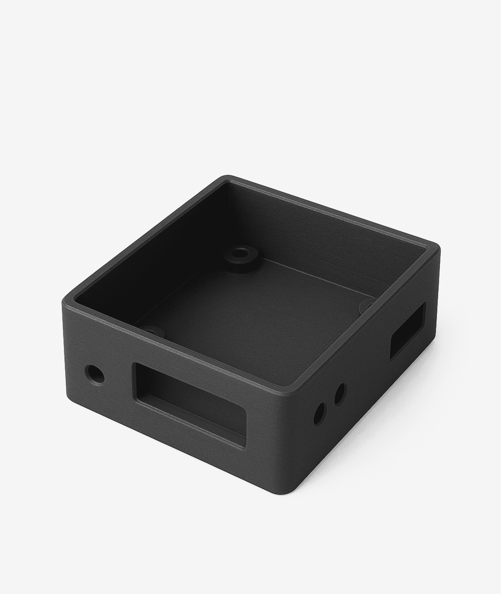
Jigs and fixtures. Assembly jigs, positioning templates, locating fixtures for conveyor line operations. Instead of ordering machined metal parts -- print from PA-CF or PC-ABS.
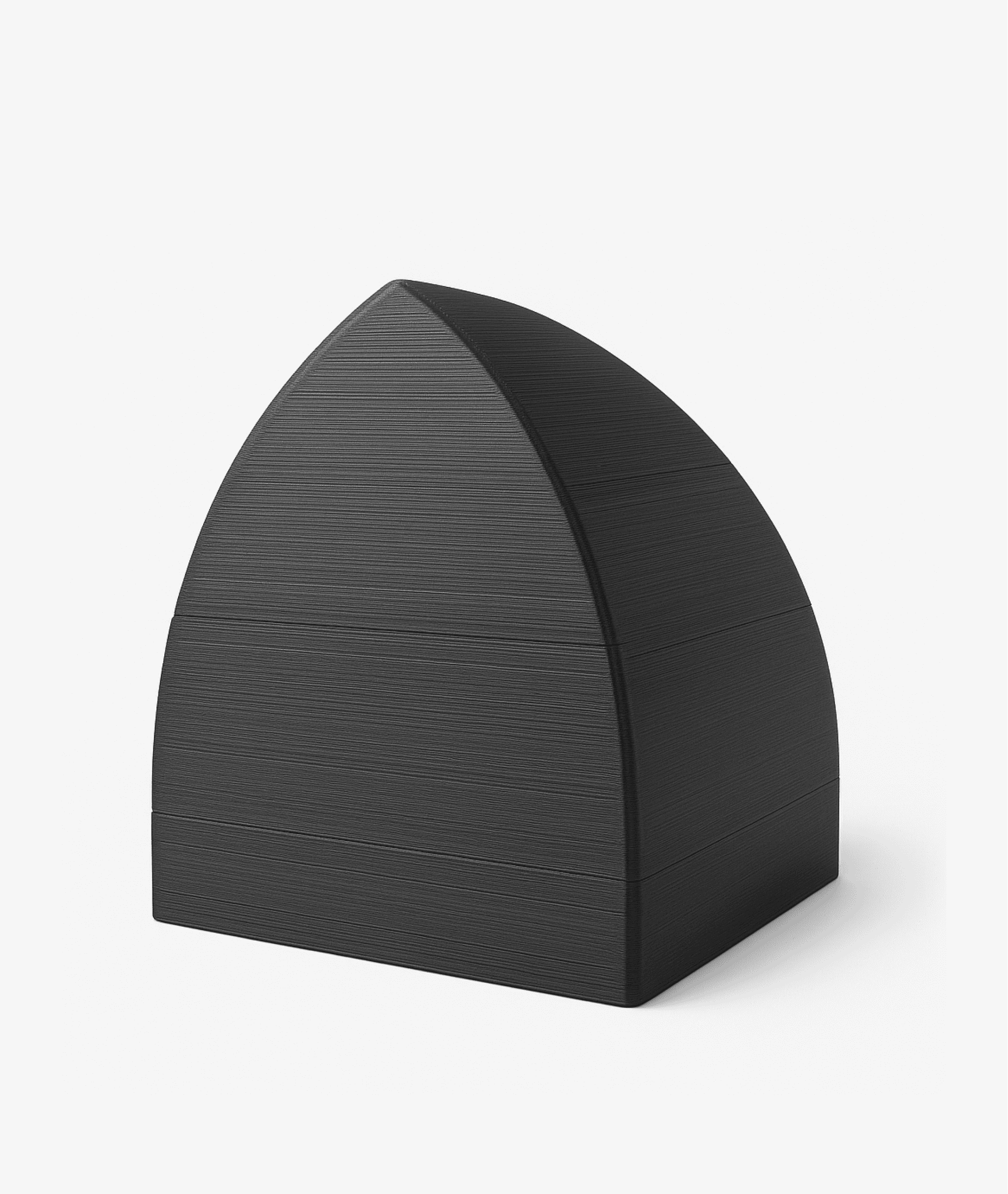
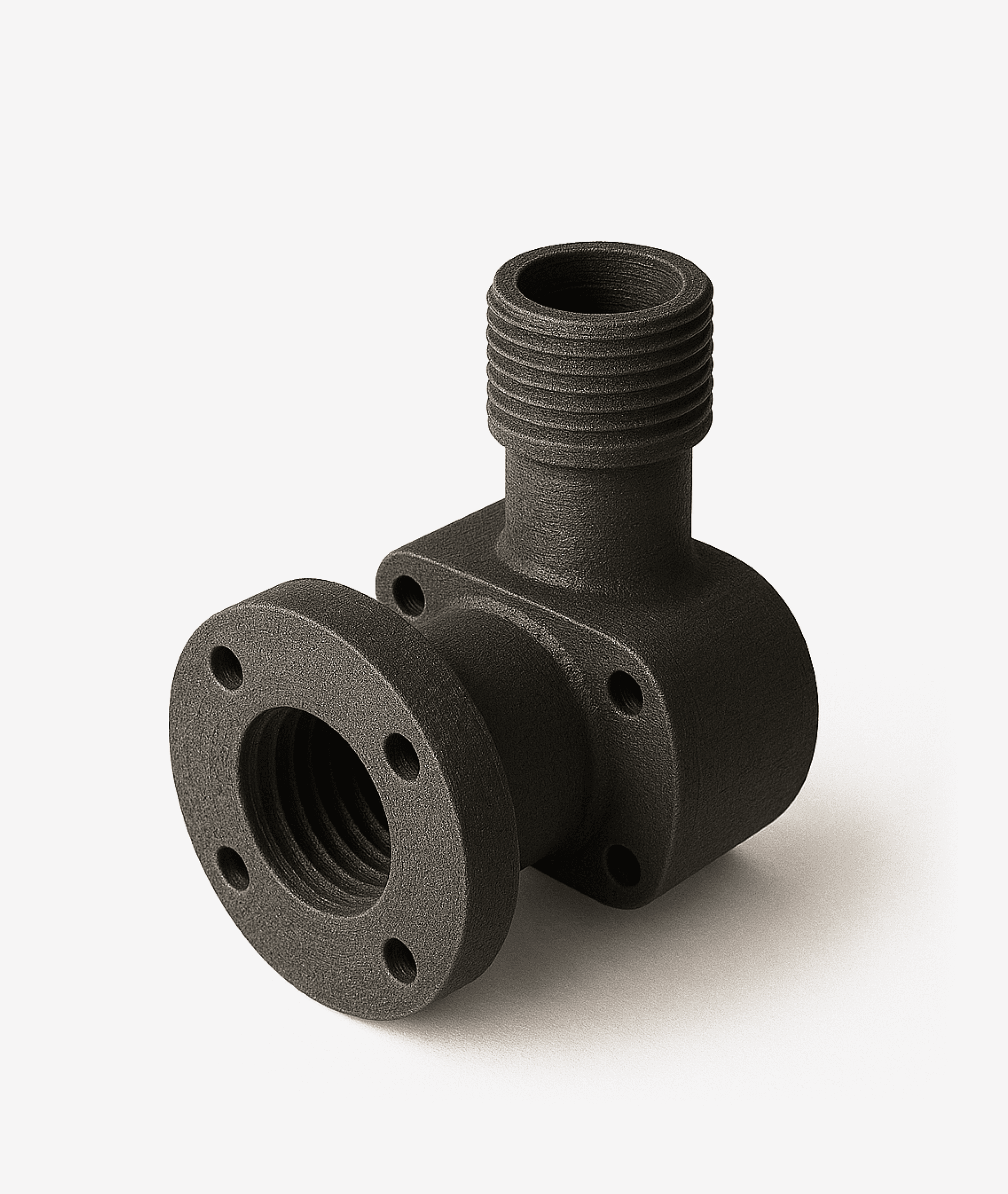
Maintenance and repair parts. Brackets, guide rails, housing covers for legacy or discontinued equipment. Reverse-engineered from 3D scans or technical drawings.
Assembly prototyping. Verifying geometry, fits, and layout ahead of series production. Multiple design iterations in days rather than months.
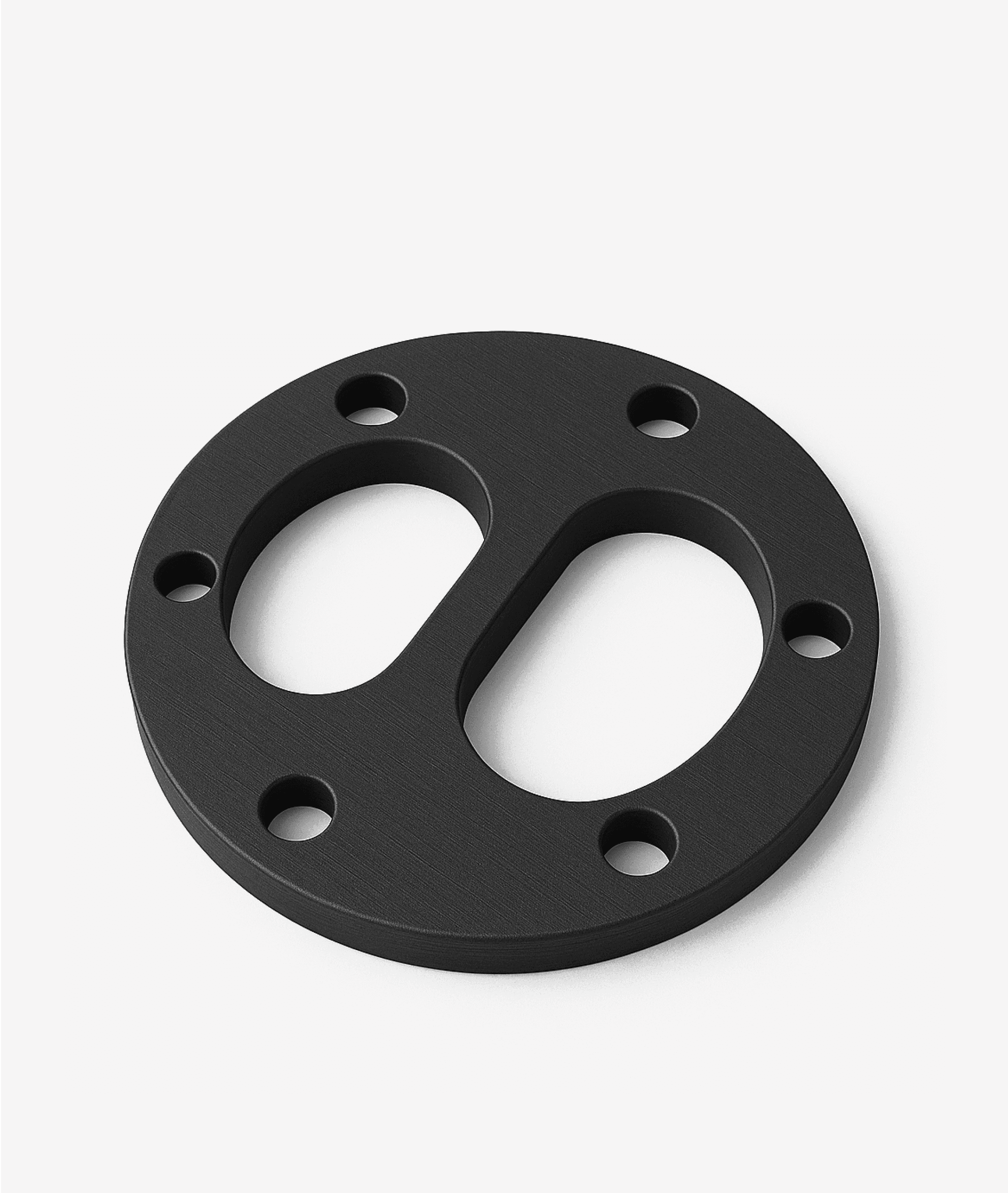
Low-volume production parts. Clamps, brackets, guides, gearbox housings -- batches from 1 to 200 units without mold tooling investment.
Spare parts on demand. Storing a part as a digital file instead of maintaining physical warehouse inventory. Print as needed.
Auxiliary tooling. Gauges, templates, machine guards, custom workholding elements for non-standard workpieces.
When 3D printing is particularly valuable in mechanical engineering
The part is needed in a single unit or small batch
The original supplier no longer manufactures the component
Mold tooling lead time does not fit the maintenance schedule
Multiple geometry variants need validation before committing to series production
Production Application Scenarios
01
Jigs and fixtures
An assembly station requires a locating jig for a new part variant. The traditional route: draft a drawing, order CNC machining, wait 2-4 weeks. With a 3D printer: the design engineer prepares a CAD model, and PA-CF printing completes in several hours. If the geometry does not fit the application -- the model is adjusted and reprinted the following day.
02
Repair parts for discontinued equipment
A guide rail on an imported CNC machine has failed, and the original part is no longer available. The component is scanned or modeled from measurements, then printed in PC-ABS. The machine is returned to service within 24 hours. The digital model is archived -- if the part fails again, it can be reproduced without repeat engineering work.
03
Pre-production assembly prototyping
The engineering department is developing a new drive assembly. Before committing to metal fabrication, the team needs to verify the layout, fastener access, and cable routing. A full-scale prototype in ABS is printed overnight and assembled the following morning. Over the course of a week, 3-4 design iterations can be completed -- compared to a single iteration per month with conventional methods.
04
Low-volume functional parts
A facility needs 50 specialized clamps for non-standard tooling. Ordering an injection mold is not economically justified at this volume. Printing from PA6 using two independent extruders in Copy mode allows two parts to be produced simultaneously, effectively doubling output per shift.
Want to evaluate whether 3D printing is a fit for your application?
Reduced lead times. Tooling and prototype fabrication can typically be shortened by 5-10x compared to conventional methods. An engineer can receive a physical part the same day or the next morning, rather than waiting weeks.
Minimized equipment downtime. A repair part printed on demand enables consideration of restoring equipment operation without extended waiting periods for component delivery.
Optimized inventory management. Instead of warehousing hundreds of rarely used spare part SKUs, organizations can maintain a digital parts library and print components as requirements arise.
Design flexibility. 3D printing removes certain constraints associated with molding and machining. This enables consideration of geometries that would be prohibitively expensive or impossible with traditional methods: lattice structures, internal channels, and multi-part consolidation into single components.
3D Printing and Artificial Intelligence: Practical Applications
The combination of additive manufacturing with AI and machine learning tools opens additional possibilities for manufacturing operations. These are not distant-future concepts -- several approaches are already being applied in practice.
Generative design and topology optimization. AI-driven algorithms can propose part geometries optimized for stiffness and weight under specified load conditions. This is particularly relevant for brackets and structural elements: the software generates forms that are difficult to achieve through milling but can be printed on an FFF system.
Quality control and defect detection. Machine vision and data analytics systems can help identify print defects (delamination, under-extrusion, warping) at early stages. A printer-integrated camera, combined with image analysis algorithms, enables consideration of automated in-process monitoring.
Predictive maintenance and spare parts planning. Neural network models trained on equipment failure data can help forecast which components will require replacement in the near term. The part is printed proactively -- before the failure occurs, not after.
Print parameter optimization. Machine learning algorithms can identify optimal parameter sets (temperature, speed, part orientation, support structure) for a given material and geometry, reducing the number of test prints and material waste.
Production scheduling. When managing a fleet of printers, AI can help distribute print jobs across machines based on priorities, utilization rates, and remaining material, improving overall equipment efficiency.
Why Protype CD400 and CD400HT
Stability and repeatability. An active heated chamber (up to 90 degrees C on CD400, up to 150 degrees C on CD400HT with uniformity of delta T < 1 degrees C) provides controlled printing conditions. XY positioning accuracy of 5 microns / Z of 2 microns delivers the geometric precision required for tooling and functional parts.
Engineering materials without restrictions. Open material architecture -- no vendor lock-in for filament supply. The CD400 supports ABS, PET-G, PA-6/11/66, PA-12/PA-CF, PC-ABS, TPU, CARBEX, and ULTRAN. The CD400HT adds PEEK, PEKK, and ULTEM 9085/1010. Integrated drying chambers (2x up to 80 degrees C on CD400, up to 130 degrees C on CD400HT) keep moisture-sensitive materials in optimal condition.
Production-grade autonomy. IDEX -- two independent extruders. Copy and Mirror modes effectively double output per shift. Automatic filament feed (4x 3 kg spools) supports unattended operation for over 10 days. Automatic bed leveling, nozzle cleaning, and an integrated monitoring camera allow the printer to operate with minimal operator intervention.
R&D and production on a single platform. Nozzle range of 0.3-1.2 mm and layer thickness of 0.05-0.75 mm allow the same printer to handle precise prototypes and rapid printing of large parts. Print speed up to 300 mm/s, volumetric flow rate up to 60 mm cubed/s.
CD400 vs. CD400HT Comparison
Parameter
CD400
CD400HT
Build volume
400x400x400 mm
350x350x400 mm
Chamber temperature
Up to 90 °C
Up to 150 °C (ΔT < 1 °C)
Bed temperature
Up to 150 °C
Up to 250 °C
Hotend temperature
Up to 550 °C
Up to 550 °C
Drying chambers
2x up to 80 °C
2x up to 130 °C
Key materials
PA-CF, PC-ABS, ABS, PA6, TPU
PEEK, PEKK, ULTEM + all CD400 materials
Recommended for
Tooling, prototypes, low-volume runs
High-temperature parts, super-polymers
Warranty
12 months
12 months
Try & Buy: 3-month evaluation program
Protype offers a Try & Buy program: use the printer in your own production environment for 3 months, and if you purchase, 100% of the rental cost is credited toward the purchase price. Minimal risk -- maximum opportunity to evaluate real-world impact.
Frequently Asked Questions
Ready to evaluate how 3D printing fits into your production workflow?
You can also take advantage of the Try & Buy program: 3 months of on-site evaluation with 100% of rental costs credited toward purchase.